How low can it go? (optimizing for power)
Background
The Arduino (and later the Raspberry Pi) have created a huge marketplace of kits, modules and discrete parts. Vendors all over the world offer a large selection of sensors, displays, motor controllers and micro controllers for every need. This has opened up huge opportunities for individual makers to experiment and learn. Devices like these used to be very difficult to source and use in single piece quantities. If you're on a tight budget and have a lot of patience, vendors in China are willing to sell low quantities of parts directly to you at prices much lower than local vendors can offer. Over the last few years, one of my personal goals has been to familiarize myself with "The IoT". This has mostly involved buying parts, reading the datasheet, writing software to drive it and then sharing the results on GitHub. The only way I've been able to afford to acquire and test all of these parts is by buying them from China. My mailbox receives a steady stream of black and gray plastic envelopes and both the vendors and the mail have been extremely reliable. Recently I've found a practical application for this experience and have been creating prototype projects that will hopefully turn into commercial products. The current project I'm working on will be powered by a battery and needs to be as efficient as possible.
Hitting the limits of a 'hobbyist' maker
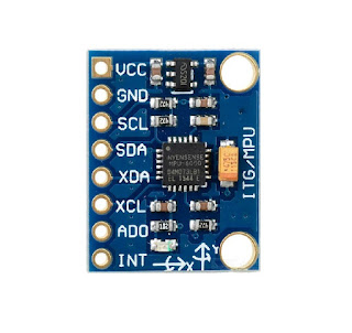
A common aspect of these hobbyist parts is that they're designed for easy experimentation and for people with very little experience. That means that they come packaged on pre-made printed circuit boards with indicator LEDs, voltage regulators and 0.1" through holes to make them easier to use and harder to mess up. This is helpful for the majority of use cases, but what if you're making a battery powered prototype and need everything to be as power efficient as possible? The datasheet for a part (e.g. MPU-6050 accelerometer/gyroscope shown below) may say that it only uses 5uA when idle, but when sitting on a development board with a power indicator LED and 3.3v regulator, it uses a lot more than 5uA.
In my case, I don't have the tools or experience to work with surface mount parts or create my own PCB designs (yet). Once I've created a good prototype, I'll find the right people/services to help me produce a final PCB. Until then, I've got to create prototypes with what's available to me. I'm sure I'm not alone in this situation. For a particular project I have in mind, I need a micro controller to sample an accelerometer every few minutes and report the results wirelessly at least once a day. I would like the final product to be quite small and be powered by a CR2032 lithium coin cell battery (3.25v ~220mAh). If I want to run my product on this battery for 100 days, then I have a power budget of about 2.2mAh per day (about 92uA continuous drain). My software won't need to do much work or fancy calculations, so a simple 8-bit MCU like the Atmel AVR series would work fine.
Real World Results
I decided to use the ATmega328P for the heart of my device. It's able to do the job, costs very little and has pretty low power sleep modes that should provide what I need. The MPU-6050 accel/gyro also suits the project for its low cost and low power usage. The MPU-6050 is a good place to start. I used a board nearly identical to the one in the photo above. As shipped, it draws 1.39mA when idle. The little green power LED near the bottom edge of the board is using most of that. After removing the LED, the idle current dropped to 44uA. The carrier board has a 3.3v voltage regulator (4A2D) between the VCC input pin of the carrier board and the VCC input of the accelerometer. This is a very common little part found on many inexpensive circuit boards. It's pretty efficient in the middle of its range (%80), but efficiency drops off on the low end. Since I'm going to supply the board with 3.25V, there's no need for a regulator. After removing the regulator and soldering on a little bridge from the previous input to output, now the measured idle current of the board is 5uA - exactly what's stated in the datasheet. Here's the photo of my modified MPU-6050 board (LED and regulator removed).

Next up is the MCU. I sourced these inexpensive Arduino Pro Mini clone boards from China for about $2 each. The MCU is genuine (there are ATmega clones available).
 As you can see in the photo, there's a small LED near pin 9 (connected to SCK - D13) and a power LED right below the pin 1 white dot of the MCU. The 4A2D 3.3v regulator (same one used on the IMU board above) is just below the power LED. This board comes pre-configured to run at 8Mhz with a VCC of 3.3V. Just for kicks, I tested the power usage of the board before I modified the software or hardware. The board comes with the standard Arduino bootloader pre-installed and the blink sketch. The current usage measured around 4.7mA (with only the power LED lit). This is running the MCU continuously with no power saving measure employed. After removing the power LED, the current dropped to 3.7mA. Now it's time to consult Nick Gammon's excellent guide on power saving measures for AVR micro controllers. For my purposes, I need the CPU to be asleep most of the time, but I also need the RAM to remain powered up. This means that the watchdog sleep seems to be the most practical for my needs. In this mode, I can sleep the CPU for 8 seconds at a time and reduce the current usage to 6.54uA (according to Nick). There is a lower power sleep mode, but it would lose the contents of RAM and require an external signal to wake up (and reset) the CPU.
After loading the 'watchdog sleep' sketch onto my modified board, I measured a current draw of 124uA while sleeping. This is quite a bit more than the 6.54uA I was expecting. In this case, I'm powering the board through the VCC pin which skips the regulator (the RAW pin input goes through the 3.3V regulator). It seems likely that current is leaking back through the output pin of the regulator. After removing the regulator (no need to bridge the input to the output since I'm feeding power into the VCC pin), the sleep current draw measured 4uA. I'm not sure why this is measuring better than the amount stated in Nick's blog post. It's possible that the silicon fabrication process used in the latest set of ATmega328P's is a little more efficient than the one used a few years ago. In any case, I'm not complaining about it using less power than expected. Here's a photo of the Arduino Pro Mini board after my modifications.

My final power usage numbers:
MCU: 4uA when asleep
IMU: 5uA when idle
wireless part: 2uA when idle
-----------------------
Total: 11uA
I didn't include details of the wireless part of my project because it's very efficient and doesn't require any modification for my needs. The active times of these parts will be a small percentage of the total time, so it looks like my project will easily survive more than 100 days on a single coin cell battery.
The Arduino (and later the Raspberry Pi) have created a huge marketplace of kits, modules and discrete parts. Vendors all over the world offer a large selection of sensors, displays, motor controllers and micro controllers for every need. This has opened up huge opportunities for individual makers to experiment and learn. Devices like these used to be very difficult to source and use in single piece quantities. If you're on a tight budget and have a lot of patience, vendors in China are willing to sell low quantities of parts directly to you at prices much lower than local vendors can offer. Over the last few years, one of my personal goals has been to familiarize myself with "The IoT". This has mostly involved buying parts, reading the datasheet, writing software to drive it and then sharing the results on GitHub. The only way I've been able to afford to acquire and test all of these parts is by buying them from China. My mailbox receives a steady stream of black and gray plastic envelopes and both the vendors and the mail have been extremely reliable. Recently I've found a practical application for this experience and have been creating prototype projects that will hopefully turn into commercial products. The current project I'm working on will be powered by a battery and needs to be as efficient as possible.
Hitting the limits of a 'hobbyist' maker
A common aspect of these hobbyist parts is that they're designed for easy experimentation and for people with very little experience. That means that they come packaged on pre-made printed circuit boards with indicator LEDs, voltage regulators and 0.1" through holes to make them easier to use and harder to mess up. This is helpful for the majority of use cases, but what if you're making a battery powered prototype and need everything to be as power efficient as possible? The datasheet for a part (e.g. MPU-6050 accelerometer/gyroscope shown below) may say that it only uses 5uA when idle, but when sitting on a development board with a power indicator LED and 3.3v regulator, it uses a lot more than 5uA.

In my case, I don't have the tools or experience to work with surface mount parts or create my own PCB designs (yet). Once I've created a good prototype, I'll find the right people/services to help me produce a final PCB. Until then, I've got to create prototypes with what's available to me. I'm sure I'm not alone in this situation. For a particular project I have in mind, I need a micro controller to sample an accelerometer every few minutes and report the results wirelessly at least once a day. I would like the final product to be quite small and be powered by a CR2032 lithium coin cell battery (3.25v ~220mAh). If I want to run my product on this battery for 100 days, then I have a power budget of about 2.2mAh per day (about 92uA continuous drain). My software won't need to do much work or fancy calculations, so a simple 8-bit MCU like the Atmel AVR series would work fine.
Real World Results
I decided to use the ATmega328P for the heart of my device. It's able to do the job, costs very little and has pretty low power sleep modes that should provide what I need. The MPU-6050 accel/gyro also suits the project for its low cost and low power usage. The MPU-6050 is a good place to start. I used a board nearly identical to the one in the photo above. As shipped, it draws 1.39mA when idle. The little green power LED near the bottom edge of the board is using most of that. After removing the LED, the idle current dropped to 44uA. The carrier board has a 3.3v voltage regulator (4A2D) between the VCC input pin of the carrier board and the VCC input of the accelerometer. This is a very common little part found on many inexpensive circuit boards. It's pretty efficient in the middle of its range (%80), but efficiency drops off on the low end. Since I'm going to supply the board with 3.25V, there's no need for a regulator. After removing the regulator and soldering on a little bridge from the previous input to output, now the measured idle current of the board is 5uA - exactly what's stated in the datasheet. Here's the photo of my modified MPU-6050 board (LED and regulator removed).

Next up is the MCU. I sourced these inexpensive Arduino Pro Mini clone boards from China for about $2 each. The MCU is genuine (there are ATmega clones available).

After loading the 'watchdog sleep' sketch onto my modified board, I measured a current draw of 124uA while sleeping. This is quite a bit more than the 6.54uA I was expecting. In this case, I'm powering the board through the VCC pin which skips the regulator (the RAW pin input goes through the 3.3V regulator). It seems likely that current is leaking back through the output pin of the regulator. After removing the regulator (no need to bridge the input to the output since I'm feeding power into the VCC pin), the sleep current draw measured 4uA. I'm not sure why this is measuring better than the amount stated in Nick's blog post. It's possible that the silicon fabrication process used in the latest set of ATmega328P's is a little more efficient than the one used a few years ago. In any case, I'm not complaining about it using less power than expected. Here's a photo of the Arduino Pro Mini board after my modifications.

My final power usage numbers:
MCU: 4uA when asleep
IMU: 5uA when idle
wireless part: 2uA when idle
-----------------------
Total: 11uA
I didn't include details of the wireless part of my project because it's very efficient and doesn't require any modification for my needs. The active times of these parts will be a small percentage of the total time, so it looks like my project will easily survive more than 100 days on a single coin cell battery.


The "4A2D" 3.3v regulator is a LN1134. http://www.natlinear.com/uploadfiles/2014/LN/LN1134_E.pdf
ReplyDeleteCan you help me measure the consumption of a pi pico with a esp8266, a mpu6050 and a ds18b20 ?
ReplyDeleteCurrent measurement can be done with an ammeter, but to really see what's going on with MCUs you can use something like the Nordic Power Profiler Kit II.
DeleteWill look at that, thanks. I would like to use 2 xx2032 (serial) and a zenner to have 4.8v. Smaller than a 18650 or a 16340
DeleteHey man, thank you for this post, very useful !
ReplyDelete